Frequently asked questions
What is the PipeTrack?
What does the autonomy of the system refer to?
In what type of utilities can I use the PipeTrack Pipeline Mapping System?
Which bending radius can the PipeTrack pipeline mapping system pass?
Forthcoming Systems
How is the system propelled?
Does the pipe need to be empty?
Can I use it in pressurised pipes?
Do I always HAVE to know the entry and end coordinates?
What is the requirement for site preparation?
What is the operational procedure of mapping?
How long does the mapping typically take?
How long does the data processing take?
What is the output format?
What is the maximum length of a run?
What is the system's standard tolerance?
Can the standard accuracy be improved?
What is the benefit of digital data?
How does the system compare to a walk-over electromagnetic probing mapping system?
How does the system compare to CCTV cameras?
How can I save money using this system?
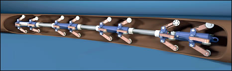
What is the PipeTrack?
- The PipeTrack is an autonomous, gyroscopic-based Pipeline Mapping System designed to determine the 'XYZ' location of (underground) utility pipes
- Due to the interchangeable wheel units, the standard system is capable of mapping pipes with Internal Diameters (ID's) of 50mm to 2.5metres
What does the autonomy of the system refer to?
While the PipeTrack Pipeline Mapping System travels through a pipeline section, all logging data is stored inside the system.
- There is no tethering of a power or data cable (such as for CCTV cameras)
- The system does not need to be traced above ground, as required with current electromagnetic systems. In other words, it is not necessary to know where the system IS as it moves from A to B, the system will calculate afterwards where it HAS BEEN
As a result, the PipeTrack Pipeline Mapping System can move through pipes:
- Quickly (up to 4.0m/sec)
- Without the need to close off streets other than at access points
- At any depth
- Within any length of pipe, duct or tunnel
In what type of utilities can I use the PipeTrack Pipeline Mapping System?
The simple answer is:- Any type of pipe with ID of 50mm or larger:
- HDPE
- Steel
- Concrete
- PVC
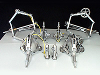
Various wheelsets available to cover the range of ID's are listed below, as well as system weight and length.
| Product Code | From ID (in) | System Weight* |
| SA50S17 | 85mm | 3.0kg |
| SA50S35 | 150mm | 3.0kg |
| SA90S35 | 200mm | 4.3kg |
| SA90S70 | 300mm | 4.9kg |
| SA140S80 | 375mm | 6.2kg |
| SA140S150 | 525mm | 6.8kg |
| SA185S190 | 600mm | 8.0kg |
Which bending radius can the PipeTrack pipeline mapping system pass?
The PipeTrack is a scalable Pipeline Mapping System and therefore does not have a bending radius!
The bending radius is dependent on the relationship between the inner diameter of the pipe (D), the outer diameter of the probe housing (d) and the wheelbase of the probe (L).
As the inner diameter D increases, the wheelbase L will be more or less constant so the bending radius will decrease as shown in the chart below.
Once D exceeds 300mm, the minimum bending radius required drops below 1 meter, at D = 650mm, the bending radius approaches 1D.
Forthcoming Systems
A new articulated system has already been developed that will allow PipeTrack to negotiate acute bends, even in smaller diameter pipes.
This system is only envisaged to be used within pipe sizes ranging from 150mm diameter, up to 300mm diameter.
How is the system propelled?
The safest way to move the PipeTrack Pipeline Mapping System from A to B is by means of pulling a wire or tether. In a smooth lined, empty pipeline the following guidelines can be followed:
- Up to 400m: Manual winch
- Up to 800m: Power assisted light winch
- Up to 1500m: Power assisted winch
Heavily corroded steel pipes, concrete pipes, and sewer pipes containing sediments will influence the pulling force required and thus shorten the above guidelines.
Be aware that the pulling force on the system does not exceed 100lbs!
Alternatively, the system can be moved through a pipe using compressed air (assistance). PipeTrack can not give guidelines on how to deploy this method as the situation varies from case to case.
Pumping the system through the pipe is a third possibility but the standard design of the PipeTrack Pipeline Mapping System does contain a high pressured casing.
Does the pipe need to be empty?
Not necessarily, but it is much easier to use the system if the pipe is empty. However, it is possible for the pipe to be filled with water or effluent.
Can I use it in pressurised pipes?
The standard PipeTrack Pipeline Mapping System CANNOT be used in pressurised pipes. However, there are systems available that will allow entry up to pressures of +4.0Bar, hence in the future, it will be possible to undertake live insertion work on water, gas and similar product pipelines.
Do I always HAVE to know the entry and end coordinates (or: can the system be used one way)?
Simple answer:- Preferably yes.
However, it is possible to obtain a result using ANY two known coordinates (of which ONE is of course the entry point). The processing procedure in this case is more complex.
- Note 1: If the exit point is inaccessible from the surface but the coordinate can be obtained, the run is actually a standard run. The field technician simply has to stop the system at the end point, let it rest for 30 seconds and then pull it back
- Note 2: When working only with an entry point be aware that the range of the run is limited to how far you can push the system into the pipe. The smaller the diameter, the further you can push it in
More recent developments now enable a pipe to be mapped from a single point of entry, where an initial angle bearing can be provided. This will enable the mapping of many pipelines such as pumping mains which are commonly omitted or inaccurately recorded on public utility drawing records.
What is the requirement for site preparation?
The client is typically asked to prepare the following:
- Acquire necessary (local) permissions
- Implement safety requirements
- Ensure entry and exit points are easily accessible and have at least 15ft of working space in line with the pipe.
- Optional: Introduce a pulling wire into the pipe
- Optional: Obtain entry and exit point coordinates
What is the operational procedure of mapping?
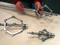
- The correct wheel set is selected to fit the pipe ID
- The PipeTrack Pipeline Mapping System is switched into logging mode
- The system is connected to the pulling cord (safety cord is connected to the rear of the system)
- The system is placed into the pipe's entry point and the rear is aligned with the beginning of the pipe (see picture above)
- A 30-second 'stable period' is observed
- The system is pulled through the pipe to the end point until the front reaches the end of the pipe (see picture above)
- A 30-second 'stable period' is observed
- The system is taken out of the pipe and the data is either uploaded to a PC or the system is turned around for a return run (back to step 3)
How long does the mapping typically take?
If the correct preparations were made, typical mapping takes around one hour, assuming 4 measurements of runs up to 1000ft. Longer runs may take up to two hours.
How long does the data processing take?
Per run, the processing takes about 15 minutes.
What is the output format?
Two standard output formats are programmed:
- Comma Separated Value (.csv). This format is the most open format available and can be seamlessly loaded into Excel, ArcView and several other applications
- Script Format (.scr). This is the default format for AutoCAD, allowing instant upload into AutoCAD or similar CAD software systems
In addition, the software has a pre-programmed Profile View and all Graphics viewed during processing can be saved for later review.
What is the maximum length of a run?
There is no definitive run length. The achievable length is largely dependent on the shape of the pipe (e.g. sharp bends reduce the achievable length) and the mode of propulsion.
It is, however, advisable to have available intermediate coordinates for very long runs (similar to the requirements of intelligent pigging applications).
What is the system's standard tolerance?
A tolerance in X and Y is 0.25%, and 0.1% in the Z areas (level of pipe) of the surveyed distance between known points.
Some observations:
- In practice, the accuracy of the depth (Z) measurement is better than the XY plane
- Tolerance is determined by testing the system in a controlled above ground environment
- Tolerance is affected by excessive measuring speed and excessive forces on the system, such as from severe welds, sediment etc.
Can the standard accuracy be improved?
Multiple runs from A to B and B to A may improve the results following normal statistical reasoning. In practice, for runs longer than 100m it is advisable to obtain 3 to 4 valid runs whilst in the field, since it does not take much time and the opportunity to return at a later date for more runs is usually not available.
What is the benefit of digital data?
Digital data is time proof. In the old days, networks were mapped on paper and the location referred to landmark such as building features, many of which no longer exist. In addition, paper maps are 2-Dimensional only. The information provided by Pipetrack is 3-Dimensional data and as such can be analysed in every direction and has particular benefits for assessing vertical and horizontal alignment.
How does the system compare to a walk-over electromagnetic probing mapping system?
An electromagnetic system contains a battery operated sonde which is pulled or pushed through the pipe. The sonde emits a continuous signal which can then be picked up above ground by a receiver. The person holding the receiver marks spots on the surface at intervals which are then mapped by a surveyor topographically who then sends it to the drawing office for conversion into a CAD or GIS platform. This is a cumbersome process which still requires a probe to pass through the pipe.
Furthermore, these systems are limited to the depth they can map and are very susceptible to electromagnetic interference. They are also time consuming and costly for all but the smallest of schemes.
How does the system compare to CCTV cameras?
CCTV cameras are primarily designed to look at something, not to map. Although they sometimes have an inclinometer to measure the pitch angle of pipes, the fact that they run over the bottom surface of the pipes, which are frequently full of sediment, means that you never know for sure what the system is measuring. They are also prone to climb the side walls of the pipe, particularly on bends, which invalidates the usability of the date provided.
The combination of the PipeTrack Pipeline Mapping System and a CCTV survey in sewer environments is very powerful, particularly in cases where pipes are being rehabilitated.
Operational efficiency can be significantly increased by first mapping the sections using PipeTrack and thereafter only sending the CCTV unit into those sections that show severe deformation. Furthermore, CCTV systems are connected by power and control cables which significantly limits their operational range, normally to no more than 250m.
How can I save money using this system?
For contractors:
- The operational efficiency increases
- The risk of damage may be reduced
- Hand-over procedures can be faster and easier
For network operators/owners/engineering firms:
- Network data is better
- Multiple measurements over time will provide dynamic data of the pipeline (a movie rather than a picture)
- Dynamic data will allow operators to help define for more effective 'dynamic' maintenance programs (rather than 'static' maintenance programmes that are typical today), thus limiting the risk of pipeline failure and enhancing maintenance efficiency
| Telephone: 01702 410744 Email:utilmap@gmail.com |
 |
 |
 |
| The technology is not effected by magnetic fields or other sources of interference that can affect the accuracy of many other survey techniques. Being able to perform in this way ensures that very accurate surveys can be undertaken at a greatly reduced cost and with greater efficiency. |
-- top of page --